
A fun project to interest my daughter in electronics.
Some while ago i bought the chassis with the wheels, motor's and gearbox.
For "The Brain" i use an Arduino pro mini 328 programmed with BascomAVR.
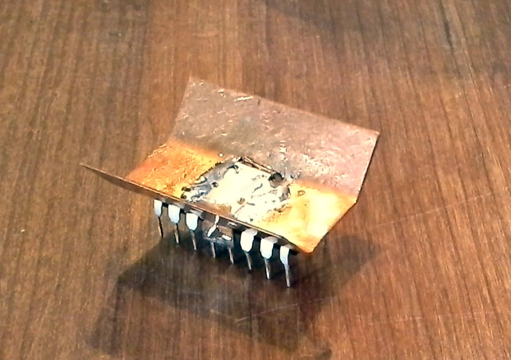
To control the motor's i applied it with an L293 . I made an heatsink from a little square
piece of coper.
 |  |
 |  |

I use 2 driver's to control one motor.
his way you can reverse the motor direction.
I supply the enable pin's with an PWM
signal from the arduino. This make's it
possible to regulate the motor speed. With
the motor speed you can of course control
the speed of the robot. But also if you
increase the speed of the left motor and
decrease the speed of the right motor, it
wil make a right turn and vice versa.
I wired an ISP connector so it's possible

Some capacitor's across the motor's
prevent interference of the remote link
As power source i used two 18650 Li-ion battery's in series which makes 7.4V. This voltage will supply the motor's. A 5V
regulator is used for the Arduino.
regulator is used for the Arduino.
To control the robot wireless, i use
two NRF24L01+ modules.
two NRF24L01+ modules.

The remote control consists of a Atmega8 also with an
NRF24L01+. With 2 potmeters i control the PWM signals
en motor direction of the robot. With the potmeter's in the
middle position the robot is motionless.
If you turn the left potmeter clockwise, the robot will
NRF24L01+. With 2 potmeters i control the PWM signals
en motor direction of the robot. With the potmeter's in the
middle position the robot is motionless.
If you turn the left potmeter clockwise, the robot will
go forward. If you turn it counterclockwise it will go
backward's. The right potmeter control's the stearing.
backward's. The right potmeter control's the stearing.
Well that's all for now. It's a functional machine but still some work to do though.
I still wait for the battery holder to arrive. The rear wheel consist of an metal ball which will
roll in all direction's. It make's a lot of noise. I planned some rubber wheels for the backside.
I have to find an enclosure for the remote. And i probably will exchange the potmeters with an
joystick.
 |
 |
 |
 |
Finally the battery holders arrived so the battery's could be properly mounted.
Each Li-Ion battery has it's one charger circuit (TP4056). An extra switch to put the robot in charging mode. I use a standard 5V USB adapter to power the charger circuit's.
I tried to install rubber weels on the rear, but that didn't work. To much friction.


